Showing posts with label 466. Show all posts

Sunday, May 17, 2015

Get on the valve train, and ride it.

CREEPY PUN TRAIN LIKES THIS PUN - AND YOUR SOUL

It sounded funny to me earlier....meh.

I'M SO CLOSE. It is absolutely killing me.  But before we get to engine fun, a quick update on the LTD column shifter madness.

So last time we met, I was attempting to locate or make my own linkage to connect the column shifter to the transmission.  

Goal: Take out that stupid "high school" janky floor shifter.   But guess what? I might be in luck! A 1975 Ford LTD just arrived at our local Pick n Pull yard.  I love an excuse to head there.  So let's go!

A trip to the junk yard...


There is something serene about going to the junk yard.  It was a sunny Wednesday morning and I made the mistake of wearing my nice jeans and shoes to go exploring.    Hey, I wore my "let's get oily" shirt so at least I won't get too filthy.

Let's go on this car safari!


Spotted in its natural habitat, (broken, on stands in a junk yard) The Lincoln Mark IV(I think), isn't quite the LTD I am looking for but it does share the same body style and hopefully the same transmission linkage!  But, No dice.   This car definitely saw some years on the road.  I could almost hear an exhausted male voice threatening to threaten a Disney road trip by "turning this thing around".

Moving on....and in all it's....yellow glory, I found the LTD lumbering about, having zero shame of how... yellow it was.


Ugh, what an ugly boat.  It was in terrible shape and a lot of it was already picked apart.  Unfortunately, I already had the type of linkage this car has.  

So that makes this visit a bust.  Anyway, on to the engine part.

This block gets a 'head' in life, or two.


Stupid joke. Hilarious Austin Powers reference.  Good enough for me.  Anyway, I'm going to put the heads on the engine now.

Head Specs for engine nerds:
  • Ported D0VE heads ported/assembled by Scott Johnson.
  • 2.08/1.65" Valves
  • rocker studs, guide plates, manganese bronze guides, p/c guide seals
  • 305/180 cfm @ .600" valve lift
Anyway, here are some pictures.


So that ring thingy at the bottom? That's a dowel.  This helps me "align" the gasket and head on the block really easily.


Next I put the "studs" in.  I already made a mistake here because I didn't read the last sentence in my "Big Blocks for Dummys" book.  You'll see in a second.


Now let's slide the head gaskets on!  Then let's place this heavy ass 100lb head on.


Um...why are those second/third bolts not even reaching past the head??

LIFE TIP #324:  READ THE ******* MANUAL - don't skim like I did.

"Oooooh. There are TWO different sizes, short go on top, long go on bottom."

Reading is dumb.  But when you're dumb, reading makes you smrt.  So read, stupid.
So after pulling both heads, redoing the bolts, then placing these 100lb heads back on, we were good to go.

(Make sure to follow proper tightening sequences!!)

Next up, the rocker arms!

PRW 1.73 ratio steel body rocker arms

Here is where everything slowed down.  There was so much to do here. 

Ugh -  Un-boxing, un-packaging things: There were over 30 individually wrapped peices here.  I wish I could have hired one of those weirdo "unboxers" guys you see on YouTube.   I don't know how these guys take such pleasure with so much unwrapping.

Yeah I don't get it either. But I do own a horsehead mask pictured above.

I took each rocker arm and locking nut, washed it in the parts washer, blow dried them all using the air compressor and then soaked them in oil per instructions.  

SIDE BAR:
Also, this is also where I found out that I hate getting my hands oily.  I don't mind getting them dirty, greasy, cut up or whatever, but I HATE getting them oily.  I hold oily things like I'm discarding a bag of dog poop.

Anyway.......

Made a nice metal soap for the big block gods.

Moving on - measure pushrod length.

Holy hell this was a big one.   So everyone in the world will tell you just to make sure the wear pattern on the valve stem is centered...but there is sooo much more to that.

First and foremost, if you have done anything different from a stock configuration - you HAVE to measure for a new pushrod length.

Variables affecting pushrod length:
  • The location of the Moon, mars and the North Star.
  • Block, head deck height
  • Studs, guide plates, gasket height...
  • kind of lifters used, hyrdo cam, etc
  • How much salt intake you had that day
Basically, you gotta measure that stuff.  How to measure it?   Hoooo boy, you're in a fun world of fun depending on where you go.

   
If you are like me and have a pre-assembled head by an expert that made sure most of that valve train geometry is in good shape, then all you have to worry about is the geometry of the roller tip to the rocker...rotating...thingy and making sure your wear pattern on the valve stem is somewhat acceptable.   If you have any questions: go visit your favorite engine building forums and read the millions of pages on "proper valve train geometry".

   
Also, don't 'prime' your lifters.  After you adjust for zero lash, that extra 1/2 to 3/4 turn on the rocker arm nut will pre-load the lifter for you.  

SIDE BAR:
Here is one thing that is common in engine building as it is in software engineering:  When attempting to learn a new concept in either one, documentation always assumes the user knows every bit of context in all situations.   Lots of "step 1: do a thing, step 2: ???, step 3: profit" bs.


Yeah, easy stuff, right?  Well, the good news is if you come across the situation, there is something that others are assuming you will do before you get to the next step.  So go out there and look at examples of people's work. Good or bad, you'll start to pick up a familiar pattern.  Then, terminology, context and a general idea will soon come to you.  You just have to dig!

Anyway...

Here I have an "adjustable" push rod for measuring what length I need.


Fast forward an eternity later and I have found my intake lengths and my exhaust lengths.  

With push rods taken care of, (on order), I'm eager and want to throw the intake and valve cover on.   Thanks to Mickey, a friend and old co-worker, we get this done on a Sunday evening.

So here is a thing I just found out:  only 460s of year 74 and up (excluding 73 trucks) have "turkey" or valley pans.  So my plan after a bit of research was to use both.  Keep the pan to prevent oil from splashing up but cut off the metal gaskets and use my own. IT WILL BE PERFECT BECAUSE I AM AN EXPERT METAL CUTTER GUY.


UGH WHATEVER YOU STUPID METAL THING. CUT IN THE DIRECTION I WANT YOU TO GO IN.

Hah! Welp.  Then I said screw it and just used the pan to make sheet metal blockages for the exhaust crossovers.  

Fast forward later and thanks to Mickey's help....Boom.


It needs some paint touch up on areas but it is looking like an engine!!

I left a ton of technical detail out so if anyone has questions, hit me up.  

Anyway, No update next week because I'm going on my honeymoon.  So see you all in a couple of weeks!

Sunday, April 12, 2015

Crankshaft goes in / Steering Column Fun

I missed an update last week. 

Well, truth is, not much really went on.  Easter hit, I also had a bunch of other things I had to take care of.  Most importantly of all, my friend who is in charge of making sure I don't do anything stupid was gone, so I wasn't about to risk burning the shop down without him.

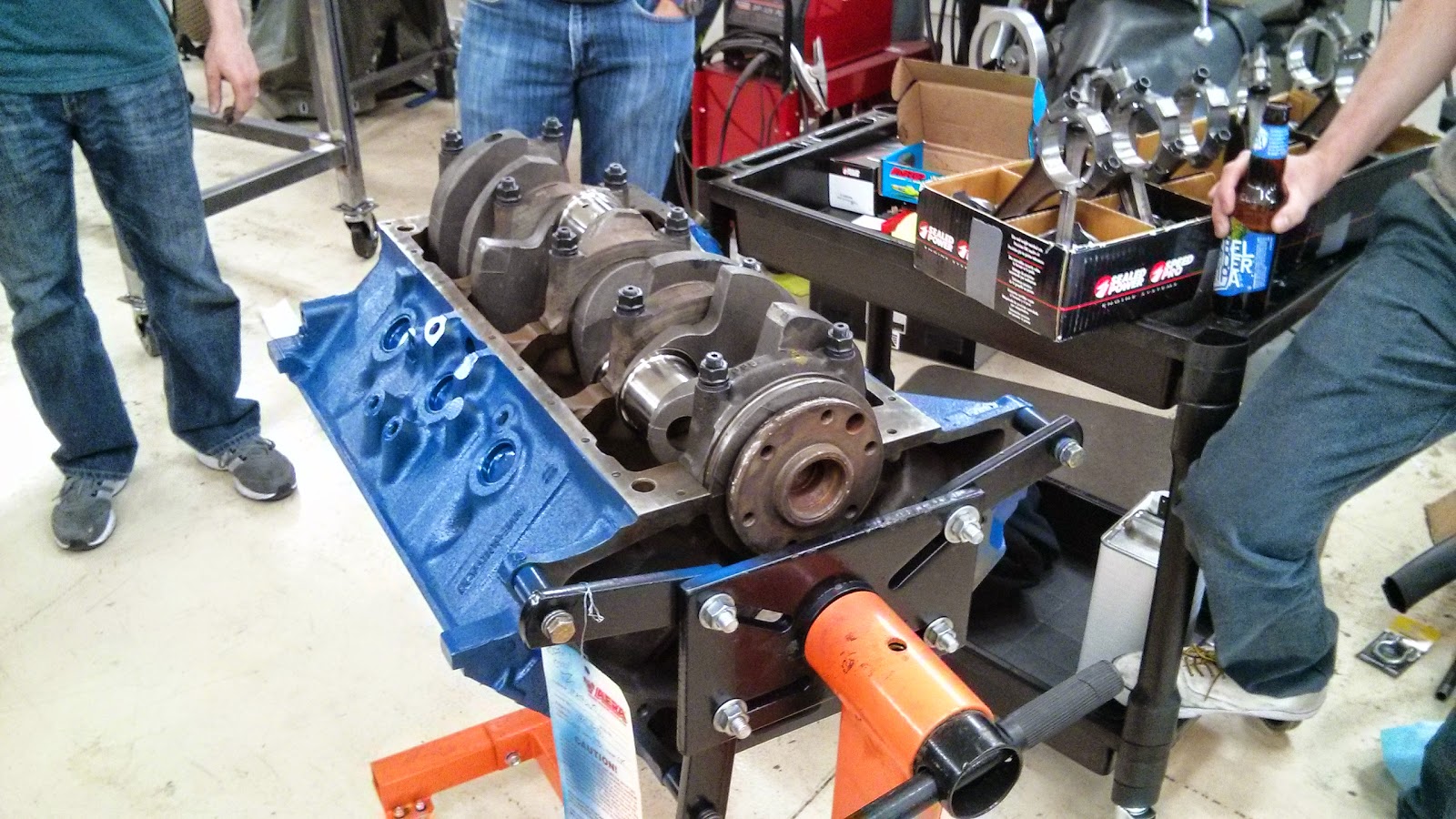
Anyway, this week was a bit better.   Time to get the crankshaft in there.


There it is, all painted up and ready to rumble.  I cleaned up everything yet again with some acetone and then we got the ARP studs in place.


Jake put the oil retainer end seal on first.

Then after the studs were put in, we lubed up the studs as well as the bearings.

Then we put the caps on and tightened it all down.


Then we got the big torque wrench out and tightened the end cap studs to spec.


Then we took a beer break and practiced some lassoing.   Don't ask.


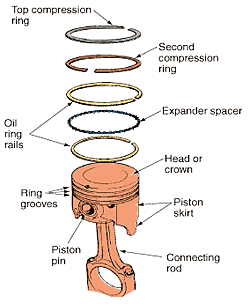
Next up, Picton rings! 4
...and I forgot to take any pictures while we were putting the piston rings on.  So here here is the only pic I got of that day before it became a blur.

So some piston ring sets have to be properly gapped using a grinder.   Basically before I put the rings on the piston, I have to make sure they are a specific gap (which can be found on your piston's spec sheet) to allow for proper expansion but not to much otherwise you'll risk losing compression and having gasses blow back into the crank.  If they are not gapped, I have to place them in the bore, measure the gap, take it out and grind it a bit, deburr the edges, place them back in the cylinder bore and measure the gap.  Rinse and repeat until it is properly gapped.

Anyway, check the picture below to get a good idea.


Anyway, all 8 pistons got em now so next time I'll be assembling the pistons on the actual crank.  Then things are really are going to move.

Steering Column Fun

A bit ago, I snagged a column from some dude on the East Coast.   Mainly because he hooked me up with all the original column shift linkage and it seemed to be a lot better condition than my current on;  My current column is a mess and the ignition harness is basically shot.   I got this for a project down the road but something came up and I gotta get this thing in now instead of later.   


Reason is I want to put an electric fuel pump in, but I don't want to do that until I can figure out why my ignition harness in the engine compartment side isn't getting any power to the (i)Ignition wire.  

Why do I need that all done?  Because I have an electric fuel pump controller that will detect when the RPMs hit a low threshold and automatically shut the pump off.  So if I roll the car, my fuel pump won't continue to pump death all over me.  

That controller and pump will be powered by when the key is in the 'ON' position.   And currently, my coil (and the rest of the car that needs that) doesn't know when the key is in the on position.

How is my coil currently being powered?  By the accessory key-on.  *nods*  Yep.  I'll get into that later but long story short, I removed all the old fire starting wiring jobs from the previous owner and ran my own fused circuit/relay powered by the battery and keyed-on by the accessory post.  
Acc Post of doom.  That yellow wire goes through the fire wall and will tell my relay when to give precious life to the rest of my ignition controlled car.

I would actually like the coil to be powered by the (I)-wire, controlled by my keyed ignition.

Check this diagram out:

I had to check that I had continuity when the key is in the on position.  So I had to reach under my dash of wiring doom to verify that the ignition harness was at least doing that....

I took the multi-meter and gave it a test.  Nothing. Dead in the water.   So that explains why the previous owner had it wired this way.  Ugh.  Well....might as well pull the column out and pull the ignition harness out of the column for more testing.....hell, while I'm at it, let's look at putting the other column in!


So in the new column, the circled stuff is my ignition switch and harness.  I gotta test those guys out before putting the new column back in. If both columns are bad, I gotta snag a new one.

But FIRST, I have to take the damn thing out.  Which is fairly simple but I didn't actually complete today.    The last bolt I needed to take out (sleeve to flex thingy or whatever) is a 12-point and not hex.  Which I have no tools for.  


This week I will snag the proper tools and hopefully get this done.  Then after that, I can install the new fuel pump too - which may be some work because I'll probably bend some new line to replace the old stuff.  As usual, I will post any major progress and keep it picture busy.

Until next time!

Sunday, March 22, 2015

Double Feature: Engine Build part 1 and Wheel Bearing Troubles


Two separate things accomplished this weekend:  Got the Crankshaft ready to bolted in and I fixed that shuddering issue I was having on the Beast!

But first...

Engine Build:  Verify Crankshaft/Main Cap clearances.

Before we can proceed, I have to make sure everything friggin fits right.  That means there has to be a Goldielocks of a gap between those big iron U-looking caps you see down there and these metal little bearings that sit on top of them.    

Educational point:
These are called the main caps and the main cap bearings.   These guys hold the crankshaft into place. So this big weighty thing that moves those pistons can spin up 5500 RPM has to have this clearance between the crankshaft journals and the bearing - it can't be too big and it can't be too small.    It's picky.  If it is too big?  The crank can bang up and down in there while spinning. If it is too small, heat/excessive wear.  Either way, it's $$$ and probably emotional weight.  No one needs that.

So I get everything organized and my buddy is supervising me making sure I don't bolt anything inside out or backwards.  

Here are the old main bolts with the main caps behind there.   I'll toss these bolts for some fresh new ARP main studs.

Fun fact: While I was doing this, he was busy upgrading his Honda Trail70 bike.
Distraction:  Jacob was currently upgrading his Honda Trail70 to a 88 I think?  New racing upper end will make that thing pop some wheelies without a doubt.


Anyway, we pop the upper half of main bearings in first.  Make sure everything is super clean of my greasy finger prints.  Seriously, specs of anything can cause wear and whatever.  Like, I'm sure my fart particles are going to take 10 years off this engine's life.


Next, we'll slap those ARP studs in place.  Finger tight.  Fun fact:  Studs make everything easier to install versus bolts as the studs literally act like dowel guides for you to just slide things into place.


Next is the plastigauge part.  These are little wax sticks that you place ON the crankshaft, then SQUISH it in place by actually installing the main caps to full torque specifications.   This will cause the wax to spread out and let you know just how much of the wax was displaced - giving you a good oil clearance reading for your bearings!

Step 1 - cut the wax into several little wax sticks.

Step 2: place stick onto each journal of the crankshaft.  NOT PICTURED: me actually making that straight before moving on.

Step 3:  Put on all the main caps and torque it into place.  Which you have to look up ARP's torque specs for those main studs.  I think was like 125 ft-lbs of torque?  Always RTFM!

Step 4: Undo everything and look at how much of the wax was squished out.  Use the cool plastigauge ruler to see if you are within clearance.  

So good news, all is well and I can proceed with the build!  Except that my engine rebuild gasket kit hasn't arrived yet (it showed up about 7pm that day) so that means we wait until next Friday.
Welp, time for a whiskey!  Or two.  Cheers.

Meanwhile...

Wheel Bearing Replacement

Symptoms I was hearing when driving the Beast:
  • Severe grinding sound when turning a quarter of the way to the left while moving forward.
  • Vibration/Shuddering at higher speeds
Someone mentioned wheel bearings to me - I figured those bearings haven't been touched in a few 10k miles so I might as well check them out.  Well, I've never done this before so...let's dive right in!!

So here is a what I will be looking at:
Mine are discs, not drums - but everything else is the same.


So first thing to do: Take the tire off.


Then, take the caliper off the rotor.  Everyone on the Internet warned me to make sure I don't just let the caliper hang there (That's not what the brake hose is for!!!)  So I propped it up on a jack stand and wired it up to a bolt for extra safety.


I take this moment to free spin the rotor without brakes or anything else holding it up.  It free spins decently I guess but it makes a weird tick tick tick noise as it spins.  It honestly reminded me how bearings sounded on my skateboard when I was younger so maybe that is what actual wheel bearings sound like too?  Hmm, we'll just have to find out.

Next, I take the grease cap off.  It came off really easy when I pried it with a screw driver.

Next, we pull off the nut lock, pull out the cotter pin and then the 'adjusting nut'.
This is literally the only thing holding your wheel on.  Also, mine was less than finger tight.  Hmm. That is why you use cotter pins - keep that bolt in place.

 With the nut off, we slide the rotor right off.

So far, there wasn't anything that threw me any obvious clues.  Though at the back was burned out gasket from the splash shield.  I also removed the splash shield as well.

More of that burned out gasket that made its way into the rotor.

So time to inspect this rotor and pop out the inner and outer bearings.

Hmm, that inner bearing seems suspect.

"There is your problem".  Not only was it completely seized up, but you can clearly identify the damage right above my thumb there.
Yuck.
Huh, well, glad I dived into this then!  Now to take the bearing cups out of the rotor.  Now, I don't have cool bearing removal tools to evenly punch it out of there so.....

I use a hammer and a punch (as well as pry bar which I used as a punch as well) and I knocked the shit out of the bearing cups until the pop out of each end of the rotor.   This is what my neighbors hear for about 15 minutes: CLANG CLANG CLANG CLANG CLANG CLANG CLANG CLANG

Now for installation!

First the outer bearing cup.  I put some goop on the outside of the cup and placed it evenly over the inner opening.  Then, I used a soft blow mallet (or whatever those rainman-sand filled things are called) and hammered the bearing cup into the hole until it was flush with the rim.
Then, I used a narrow punch to hammer it all the way into the rotor until it was seated properly.  I could tell it was at the end as the sound and feel changed immediately.

I did the same for the front bearing cup as well.

Fun story, I thought I was being clever by using the OLD bearing cup to evenly hammer the new bearing cup in...until I got that one stuck in the rotor as well.  Then I payed my stupid tax in the amount of time by having to hammer the stupid things all the way back out and start over.

The next step was to pack the bearing grease into the bearings.  Not pictured: both my hands covered in red grease while I painstakingly pack grease into both bearings.
What the bearings look like.

There is a technique for this though.  You put some goop in the palm of your hand.  Then grab the bearing so the wide side faces out towards the palm of your hand, and tap repeatedly into the grease until you see the grease come out of the other end.  Do this over and over until you got the entire bearing.  Then, rotate the bearing - and start over until the bearing is sufficiently packed.  That is what I did anyway.

Also, be cleaner than I was.  I'm sure I introduced plenty of bad dirt particles and what not while I was doing this because A) I'm not in some clean room where scientists work on ebola and B) I'm a normal person that sometimes uses his sleeve to wipe his nose when in the garage.


Bam - I pop the inner bearing in first then put the grease retainer on.  (see the diagram above)  I put that thing on by placing it flush over the opening, placing a block of wood on top of it and carefully, hammered the shit out of it, but careful not to make it all disproportional.

Back to the spindle.  I cleaned up the shield and really gave the spindle cone a clean down with some brake cleaner.

Then, greased up the bearing cups on the inside, placed a TON of grease inside the rotor between the two cups and finally placed the rotor on the spindle cone.

Then, while holding the rotor in place, placed the outer bearing in.   You hold it in place so you don't screw up the grease retainer.

Finally, placed the lock washer in place, and screwed the "adjustment"/jesus nut in place.

To place this nut back on, I spun the rotor a few times back and forth, then turned the nut to finger-tight. I repeated this several times until I could no longer tighten the nut finger tight.  Then followed the manual's instructions for torque specifications - which to me was about 1/4 of a turn after finger tight.

Popped the grease cap back on with the rubber mallet....which I remember thinking, "this isn't on all the way"


 Brake calipers, tire, etc etc.


And she is on the road!!!  Also, shuddering and grinding noise is frriggin GONE.  YES.  YES!!!

Except for one thing....

Damn it!!!  Grease cap fell off. Oh well,  $4 at NAPA next Friday.


Next weekend!

Going to try to get the bottom end completely installed!  Also, might do the passenger side wheel bearings as well.

Other car TODOs:  (will happen at some point in the near future)
  • Electric fuel pump/Control Kit (already purchased)
  • Read suspension bushings
  • Fix Brake line - has a small leak out of the control circuit outside of the booster.  
  • !!ORIGINAL STEERING COLUMN/WHEEL BEING SHIPPED TO ME NEXT WEEK!!